สัญญาณอินเทอร์เฟซของแผง PLC และแผง MCC อธิบายไว้
แผง PLC คืออะไร?
แผง PLC คือหน่วยควบคุมที่บรรจุโปรแกรมเมเบิลลอจิกคอนโทรลเลอร์และส่วนประกอบสนับสนุนต่างๆ รวมถึงเบรกเกอร์วงจร รีเลย์ SMPS ตัวกรอง หม้อแปลง และบอร์ดเทอร์มินัล
หน้าที่ของมันง่ายมาก: เชื่อมต่ออุปกรณ์ภาคสนามกับ PLC และดำเนินการตรรกะที่เก็บไว้ใน CPU เนื่องจากมันจัดการสัญญาณควบคุมกำลังต่ำ จึงต้องปราศจากอุปกรณ์ที่มีกระแสไฟฟ้าสูง การผสมโหลดความถี่สูงภายในอาจสร้างเสียงรบกวนและทำให้อิเล็กทรอนิกส์ PLC ที่ไวต่อความเสียหายได้
แผง MCC คืออะไร?
แผง MCC (Motor Control Center) จัดการด้านไฟฟ้ากำลังสูงของการทำงานของมอเตอร์ ประกอบด้วยบัสบาร์ คอนแทคเตอร์ รีเลย์ป้องกันความร้อน สตาร์ทเตอร์นุ่ม VFD และสวิตช์ไฟฟ้า
แผง MCC ช่วยให้มอเตอร์ทำงานในโหมดท้องถิ่น (ควบคุมที่แผง) หรือโหมดระยะไกล (ควบคุมโดย PLC) การออกแบบนี้แยกสายไฟฟ้ากระแสสูงออกจากแผง PLC ทำให้ง่ายต่อการติดตั้งและแก้ไขปัญหา
สำหรับโรงงานที่มีมอเตอร์จำนวนมาก แผง MCC ช่วยลดความซับซ้อนของสายไฟและเพิ่มความน่าเชื่อถือของระบบ
ทำไมต้องเชื่อมต่อแผง PLC และ MCC?
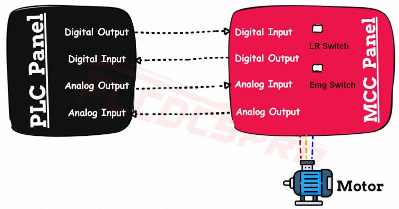
ในระบบอัตโนมัติ แผง PLC และ MCC ต้อง “สื่อสาร” กัน MCC ส่งสัญญาณตอบกลับของมอเตอร์ ในขณะที่ PLC ส่งคำสั่งควบคุม
การสื่อสารสองทางนี้ช่วยให้มอเตอร์ตอบสนองต่อตรรกะอัตโนมัติ ในขณะที่ผู้ปฏิบัติงานสามารถตรวจสอบสถานะได้แบบเรียลไทม์ เป้าหมายคือการรวมระบบควบคุมมอเตอร์ระดับภาคสนามเข้ากับระบบอัตโนมัติที่ขับเคลื่อนด้วยตรรกะอย่างไร้รอยต่อ
สัญญาณอินเทอร์เฟซทั่วไป
- คำสั่งเริ่มต้น: สัญญาณพัลส์จาก PLC ไปยัง MCC เพื่อเริ่มมอเตอร์
- คำสั่งหยุด: สัญญาณพัลส์จาก PLC ไปยัง MCC เพื่อหยุดมอเตอร์
- สัญญาณตอบกลับการทำงาน: อินพุตไปยัง PLC แสดงสถานะการทำงานของมอเตอร์
- สัญญาณตอบกลับการตัดวงจร: อินพุตไปยัง PLC แสดงข้อผิดพลาดหรือสถานะตัดวงจร
- สัญญาณตอบกลับโหมดท้องถิ่น/ระยะไกล: สัญญาณแสดงว่ามอเตอร์ทำงานในโหมดท้องถิ่นหรือระยะไกล
- สัญญาณตอบกลับสวิตช์ฉุกเฉิน: อินพุตแสดงว่าสวิตช์หยุดฉุกเฉินถูกกดหรือไม่
- สัญญาณตอบกลับสวิตช์ควบคุม: อินพุตแสดงว่ากำลังควบคุมเปิดอยู่หรือไม่
- สัญญาณตอบกลับความเร็วมอเตอร์: สัญญาณแอนะล็อกจาก VFD/สตาร์ทเตอร์นุ่มแสดงความเร็วมอเตอร์
- การควบคุมความเร็วมอเตอร์: เอาต์พุตแอนะล็อกจาก PLC ไปยัง VFD เพื่อปรับความเร็วมอเตอร์
ตัวอย่างใช้งานจริง
ลองนึกภาพระบบสายพานลำเลียงที่ใช้มอเตอร์สิบตัว มอเตอร์แต่ละตัวเชื่อมต่อกับสตาร์ทเตอร์ MCC ของตัวเอง ในขณะที่ PLC ประสานงานมอเตอร์ทั้งหมดร่วมกัน
ถ้ามอเตอร์ตัวใดตัวหนึ่งตัดวงจร MCC จะส่งสัญญาณตอบกลับการตัดวงจรไปยัง PLC จากนั้น PLC จะหยุดสายพานลำเลียงด้านบนโดยอัตโนมัติ ป้องกันการติดขัดของสินค้า
การประสานงานแบบเรียลไทม์นี้คือเหตุผลที่อินเทอร์เฟซ PLC–MCC มีความสำคัญในโรงงานสมัยใหม่
ข้อคิดสุดท้าย
อินเทอร์เฟซระหว่างแผง PLC และ MCC ไม่ใช่แค่การเดินสายไฟ แต่เป็นสะพานเชื่อมระหว่างตรรกะและกำลังไฟในระบบอัตโนมัติอุตสาหกรรม
ด้วยสัญญาณที่เหมาะสมสำหรับการเริ่มต้น หยุด ตอบกลับ และควบคุมความเร็ว ระบบจะทำงานอย่างปลอดภัยและมีประสิทธิภาพ การเข้าใจความสัมพันธ์นี้ช่วยให้นักออกแบบวิศวกรสร้างโรงงานที่น่าเชื่อถือและดูแลรักษาง่ายขึ้น
เมื่อสงสัย ให้เลือกใช้ส่วนประกอบคุณภาพและกลยุทธ์การรวมระบบที่ผ่านการพิสูจน์แล้ว—มอเตอร์และผู้ปฏิบัติงานของคุณจะขอบคุณคุณ


