Level Transmitter Installation and Calibration: A Field Engineer's Complete Guide
Covering DP, guided wave radar, and hydrostatic methods with HART configuration, zero-trim procedures, and systematic fault diagnosis
Why Level Measurement Accuracy Matters
Level measurement errors directly cause process upsets, overfills, and costly downtime. A misaligned DP level transmitter can report 10% false level, triggering unnecessary shutdowns. Correct installation and calibration prevent these failures. The Emerson Rosemount 3051CD differential pressure transmitter remains one of the most widely deployed level instruments across oil, gas, and chemical plants. Its 4–20 mA HART output demands precise installation to deliver rated ±0.04% accuracy. Understanding the three dominant technologies — differential pressure (DP), guided wave radar (GWR), and hydrostatic — helps engineers select the right approach for each vessel.
Pre-Installation Planning and Mounting Considerations
Before any transmitter goes on a vessel, the engineer must verify four critical parameters: process fluid density, operating temperature range, maximum working pressure, and required measurement span. These inputs define instrument range codes and diaphragm material selection.
For DP level transmitters, the standard wet-leg and dry-leg configurations behave differently. A wet-leg arrangement fills the high-pressure impulse line with a sealing fluid, typically glycerin or silicone oil. The static head of this fluid shifts the zero point, requiring a predictable suppression offset. A dry-leg arrangement leaves the high-pressure side open to atmosphere or vapor. This setup works when the process vapor condenses negligibly.
Step 1 — Locate the transmitter below the lower tapping point. This prevents gas pockets in impulse lines.
Step 2 — Slope impulse lines at minimum 1:12 gradient toward the transmitter. This drains liquid and prevents false readings.
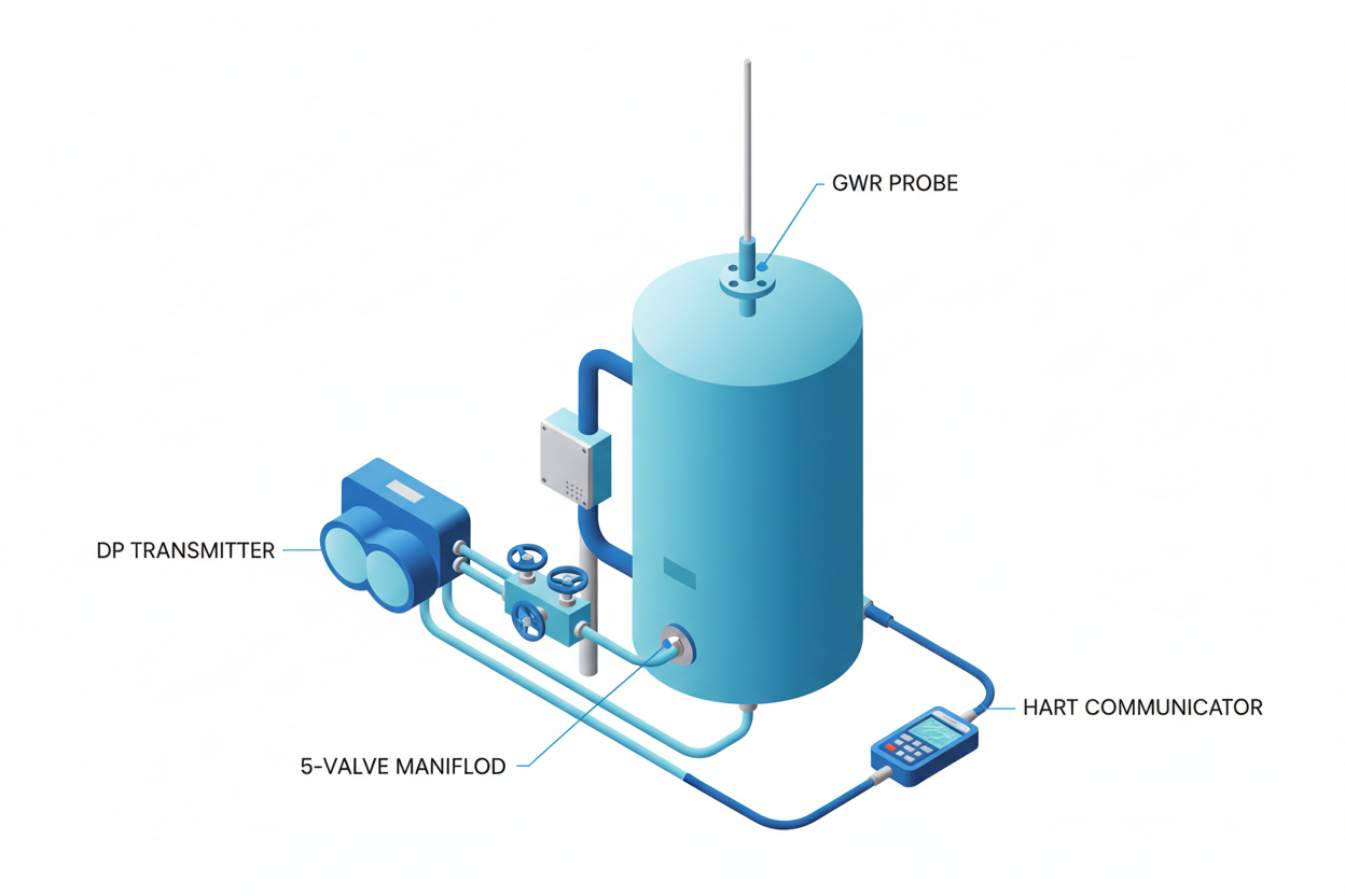
Step 3 — Install isolation valves on both tapping points. Use 3-valve or 5-valve manifolds for safe zero-trim and maintenance access.
Step 4 — Support impulse lines every 600 mm with stainless clamps. Vibration causes micro-fractures in tubing over time.
Step 5 — Verify the transmitter housing orientation. The vent plug must face upward; the drain plug must face downward to allow safe purging.
Calibration Procedure: Zero Trim and Span Adjustment
Calibration begins with a physical zero-trim under known reference conditions. For DP level transmitters, zero trim corrects for installation-induced head errors. Never perform zero trim with process fluid in the vessel unless the exact fluid density is confirmed and the trim accounts for static head offset.
The HART protocol enables full calibration without opening the instrument housing. A HART communicator — such as the Emerson 475 Field Communicator — connects across the 4–20 mA loop at any accessible terminal. The HART Device Description (DD) provides menu-driven access to calibration functions.
Standard calibration procedure for Rosemount 3051L (liquid level):
Step 1 — Open the HART communicator and navigate to Guided Setup.
Step 2 — Enter lower range value (LRV) corresponding to 0% level. This sets the 4 mA output anchor.
Step 3 — Enter upper range value (URV) corresponding to 100% level. This sets the 20 mA output anchor.
Step 4 — Apply known differential pressure at each calibration point using a dead-weight tester or precision pressure source.
Step 5 — Perform sensor trim. This adjusts the internal ADC reference to match the applied reference pressure.
Step 6 — Verify output at 0%, 25%, 50%, 75%, and 100% setpoints. Acceptable tolerance is ±0.1% of span for most SIL-rated loops.
For guided wave radar transmitters like the Rosemount 5300, calibration sets the empty reference distance and the full reference distance. The GWR measures travel time of a reflected microwave pulse, so tank geometry defines the calibration inputs. Install the probe with minimum 100 mm clearance from nozzle walls to avoid false echoes.
HIMA Safety-Rated Loops: SIL Considerations
When level transmitters feed HIMA HIMatrix or HIQuad safety controllers in SIL 2 or SIL 3 loops, additional requirements apply. The HIMA safety manual specifies proof test intervals, typically 12 months for SIL 2 DP level loops. During proof testing, engineers must verify the entire measurement chain: transmitter sensor, 4–20 mA analog input, safety logic solver input card, and the configured alarm setpoint.
HIMA HIMatrix F60 analog input cards support HART pass-through, allowing HART diagnostic data from the transmitter to flow directly into the safety system historian. Engineers can monitor sensor drift trends and membrane integrity without interrupting the live loop. IEC 61511 requires at least one full end-to-end functional test per proof test interval. Always document as-found and as-left output values for compliance review.
Troubleshooting Common Level Transmitter Faults
Frozen or sluggish output — This usually points to a blocked impulse line. Open the isolation valve slowly while monitoring output. If the signal does not respond, the impulse line contains solidified process material. Flush with compatible solvent or use steam purge per process safety procedures.
Output stuck at 4 mA or 20 mA — Check the 5-valve manifold. If the equalizing valve is open, both sides of the DP transmitter see equal pressure and output reads zero differential. Close the equalizer and verify both high and low impulse valves are fully open.
Noisy or fluctuating output — Electrical noise couples into the 4–20 mA loop when shielding is broken or grounded at both ends. Verify that cable shield connects to instrument ground at one end only. Also check damping settings via HART. For most level applications, set the damping constant to 2–8 seconds to filter process turbulence.
HART communication failure — Confirm loop resistance is within 250–1100 ohms. HART requires a minimum 230-ohm resistor across the loop. If the DCS input card provides only 50 ohms, insert an external HART resistor in series.
Conclusion and Action Advice
Level transmitter performance depends on systematic installation, precise calibration, and disciplined documentation. The combination of Emerson Rosemount hardware with HIMA safety architecture represents a proven approach for high-integrity level measurement in process industries. Always perform zero-trim before final loop commissioning, verify HART communication integrity, and maintain calibration records per IEC 61511 requirements. Scheduled proof tests catch drift before it becomes a hazard. Investing one extra hour in proper impulse line installation prevents weeks of fault-finding later.


