

Industrial Communication Topology Failures: How Design Flaws Crash Control Systems
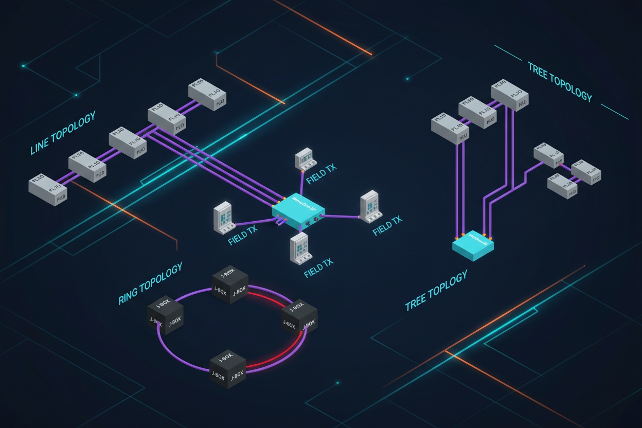
Practical analysis of line, star, ring and tree topologies in factory automation — with field proven fixes using ABB AC 800M and Profibus DP.
Why Topology Failures Matter in Industrial Networks
Industrial control systems depend on deterministic communication. A single cable break can halt an entire production line. Therefore engineers must understand how each topology behaves under failure conditions. Most textbooks cover normal operation. This article covers what happens when cables fail, nodes drop, or noise injects errors.
Modern plants combine multiple topologies. A typical refinery uses star segments off a backbone ring. When one segment fails, the ring must survive independently. If your design ignores this, a single switch failure cascades through the plant.
Line Topology Failures — The Silent Production Stopper
A bus-type line topology connects every device in a daisy chain. Engineers love it for low cable cost. However one broken link cuts the entire segment. In practice this happens more than expected. Cable crush in cable trays, connector corrosion at field junction boxes, and terminator drift all cause partial breaks.
ABB AC 800M controllers using Profibus DP report diagnostics via DP-V1 acyclic services. When a slave stops responding, the controller logs event code 16#21 (remote station failure). Technicians must then run a segment test. With a Fluke 124 or similar scope, check for reflection peaks at 10 MHz indicating impedance mismatch. A terminator resistance off-spec by more than 10% will cause intermittent retries.
Q: How do you isolate a line topology failure step by step?
Step 1: Pull the bus segment from the HMI historian. Record timestamps when tags went stale. This pinpoints the failure window to ±30 seconds. Correlate with shift logs for site activity during that period.
Step 2: Check the terminator resistors at both ends of the segment. Each terminator must read 220 ohms across the Bus+ and Bus− lines. Replace any terminator with drift above 5%.
Step 3: Divide the segment at the midpoint junction box. Use a Profibus diagnostic tool to poll each half independently. This binary search isolates which half contains the fault.
Step 4: Inspect cable glands, conduits, and junction box seals for moisture ingress. Moisture increases capacitance per meter, raising the characteristic impedance above the 150 ohm spec for Profibus DP cable Type A.
Star Topology — Isolated Failures But New Vulnerabilities
Star topology connects every device to a central switch. One cable break isolates only that device. Therefore star is preferred for critical nodes. However engineers face a new problem: the switch itself becomes a single point of failure.
In a 400 MW combined cycle plant, the DCS operator reported losing 12 pressure transmitter readings simultaneously. The root cause: a managed Ethernet switch serving the field instruments had lost power due to a fused spur failure. The switch showed no alarm. No redundancy existed at that level.
To prevent this, use ring-redundant managed switches with MRP (Media Redundancy Protocol) per IEC 62439-2. Configure two independent switch paths so that any single failure leaves a valid communication path. Set the MRP recovery time to 200 ms maximum to stay within the HMI refresh budget.
Ring Topology — High Availability With Complex Troubleshooting
Ring topology provides the best availability per cable cost. Devices forward frames in both directions. Any single cable break still allows communication around the other way. The challenge is diagnosing which device caused the ring to fail when multiple devices drop simultaneously.
Siemens S7-400H systems using Profinet IRT (Isochronous Real-Time) require ring topology for redundancy. They run MRP at 100 ms recovery time. When you insert a new device into the ring, always restart the entire ring link before bringing the device online. Skipping this step causes the HMI to lose tags for up to 90 seconds while spanning tree reconverges.
Q: How do you commission a redundant ring without tag loss?
Step 1: Document all switch port MAC addresses before making changes. Attach numbered cable labels at both ends. Photograph the existing ring wiring for reference.
Step 2: Enable port security on all managed switches. Lock each switch port to a single permitted MAC address. This prevents a rogue device from causing spanning tree re-election.
Step 3: Physically insert the new device. Monitor the HMI tag quality codes in real time. If quality drops below Good, pause the insertion immediately and troubleshoot the loop.
Step 4: After insertion, verify MRP link status via each switch's web management interface. Confirm that each device sees two redundant paths and that spanning tree has converged within 30 seconds.
Tree Topology — Hierarchical Design Requires Hierarchical Protection
Tree topology combines star and line segments under a backbone. Large plants naturally form tree structures as fieldbuses connect through marshalling panels up to the control room. The risk here is at aggregation points. A failed backbone switch can isolate entire plant sections.
Foxboro DCS systems using Foundation Fieldbus HSE often deploy tree topology at the segment controller level. Each segment controller serves up to 32 H1 fieldbus segments. If the segment controller's Ethernet uplink fails, all 32 segments lose communication simultaneously. Configure the segment controller with a redundant uplink to a second backbone switch.
When designing tree topologies, apply the N+1 redundancy rule at every aggregation level. For critical shutdown systems, use dual-redundant segment controllers connected via separate conduit runs. Do not share power supplies across redundant paths.
Conclusion & Action Advice
Industrial network topology is not a theoretical choice. Every topology creates specific failure modes. The action engineers must take: map every communication segment in your plant, identify single points of failure at switches and terminators, and apply the redundancy standard that matches the SIL level of each system. Do not wait for the first failure to discover the gap.
Document all topology changes with as-built drawings within 24 hours of commissioning. This prevents future maintenance crews from unknowingly creating new single points of failure when they replace a failed device. A disciplined approach to topology redundancy has prevented more unplanned shutdowns than any single DCS upgrade.


