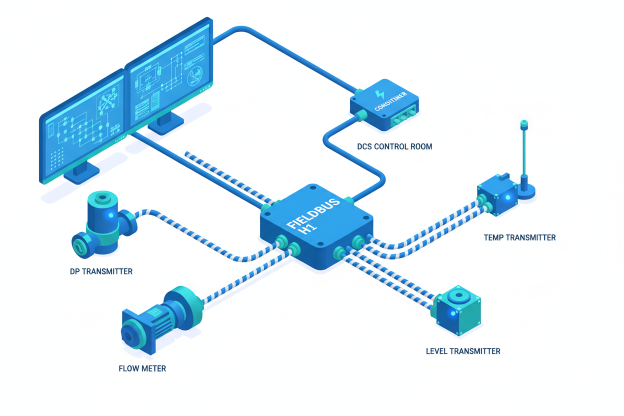
Foundation Fieldbus H1: Segment Design and Commissioning
A field engineer's guide to FF H1 segment design — covering power budget, device addressing, function block scheduling, and communication fault diagnosis.
Why Foundation Fieldbus H1 Matters
Foundation Fieldbus (FF) H1 executes function blocks inside field devices. PROFIBUS PA and HART only carry measurement values. They do not execute control in the field. In a Fire & Gas system, executing logic in the field device eliminates round-trip latency. The control function continues even if host communication fails. This is why FF H1 is still specified for SIL-2 and SIL-3 loops.
FF H1 segment design requires a power budget calculation. A segment powers 4 to 16 devices from one trunk supply. If the budget is exceeded, devices at the far end will not power up. Emerson DeltaV and Yokogawa Stardom are the two most common DCS platforms for FF H1 today.
Power Budget Calculation
Voltage drop is the primary cause of segment failure. The segment operates at 24–32 V DC nominal. Each device draws 10–25 mA. Cable resistance causes voltage drop. The voltage at the device must not fall below 9 V DC, the FF H1 minimum.
Calculate the budget before installation. Total current = sum of device quiescent currents + 10% margin. Voltage drop = total current × loop resistance. Loop resistance = 2 × cable length × resistance per metre. For 18 AWG twisted pair, resistance is 0.021 ohms per metre. For 200 metres and 12 devices at 15 mA, the drop is 1.51 V. The device voltage is 22.5 V, well above 9 V.
Consider inrush current. Some devices draw 50 mA for 50 milliseconds at power-up. A power conditioner with soft-start prevents simultaneous inrush. Emerson KJ3002X1-BA1 and Yokogawa PW302 both have soft-start limiting inrush to 350 mA per segment.
Step-by-Step Commissioning
Step 1: Verify cable continuity and insulation. Loop resistance should be less than 50 ohms for 500 metres. Insulation resistance must exceed 100 MΩ at 500 V.
Step 2: Connect the power conditioner. Set output to 24 V DC. Measure at the terminals — it should read 24.0 ± 0.5 V DC. Connect a 500-ohm resistor to simulate a load. Voltage should not drop below 23.5 V.
Step 3: Connect devices from nearest to furthest. Wait 30 seconds after each. Check the segment current readback. Yokogawa YTA310 draws 18 mA. Emerson 3051S FF draws 22 mA. If current does not increase, check wiring polarity.
Step 4: Assign permanent addresses. Devices power up with temporary addresses (17–254). Assign permanent addresses 1–16. Download the capability file (CFF) from the Fieldbus Foundation registry for each device.
Step 5: Schedule function blocks. Set the macrocycle to 500 ms for most loops, 100 ms for fast loops. Verify execution order: input blocks first, then control blocks, then output blocks.
Diagnosing Communication Faults
Total segment failure means no devices communicate. Check the power conditioner LED — red indicates overcurrent or short circuit. Disconnect all devices and measure resistance to ground. Below 1000 ohms indicates a short. Check for water ingress in junction boxes.
Intermittent device drops are the most frustrating fault. Check the segment voltage at the device with a multimeter. Below 12 V causes intermittent reset. If voltage is adequate, check for VFD interference. Route FF H1 cable at least 300 mm away from VFD cables.
Termination resistor check: FF H1 requires 100-ohm termination at each end. The power conditioner has a built-in terminator. The far-end terminator is a 100-ohm resistor in a weatherproof housing. Measure DC resistance across the segment with the power conditioner disconnected — it should read 50 ohms (two 100-ohm resistors in parallel).
Function block errors appear as “Block Alarm” in the DCS. Check macrocycle utilization. If it exceeds 80%, reduce function blocks or increase the macrocycle period. Replace slow devices or move their blocks to the DCS.
Conclusion and Action Advice
Foundation Fieldbus H1 segments need careful power budget design, correct function block scheduling, and proper cable routing. Calculate the voltage drop for the longest device. Use a power conditioner with soft-start. Schedule blocks in input-control-output order. Keep a spare FF H1 power conditioner and terminator for each plant area.


