

Control Valve Positioner Calibration: Zero, Span, and Auto-Tune Procedures for Pneumatic and Smart Positioners
Positioner Types and Operating Principles
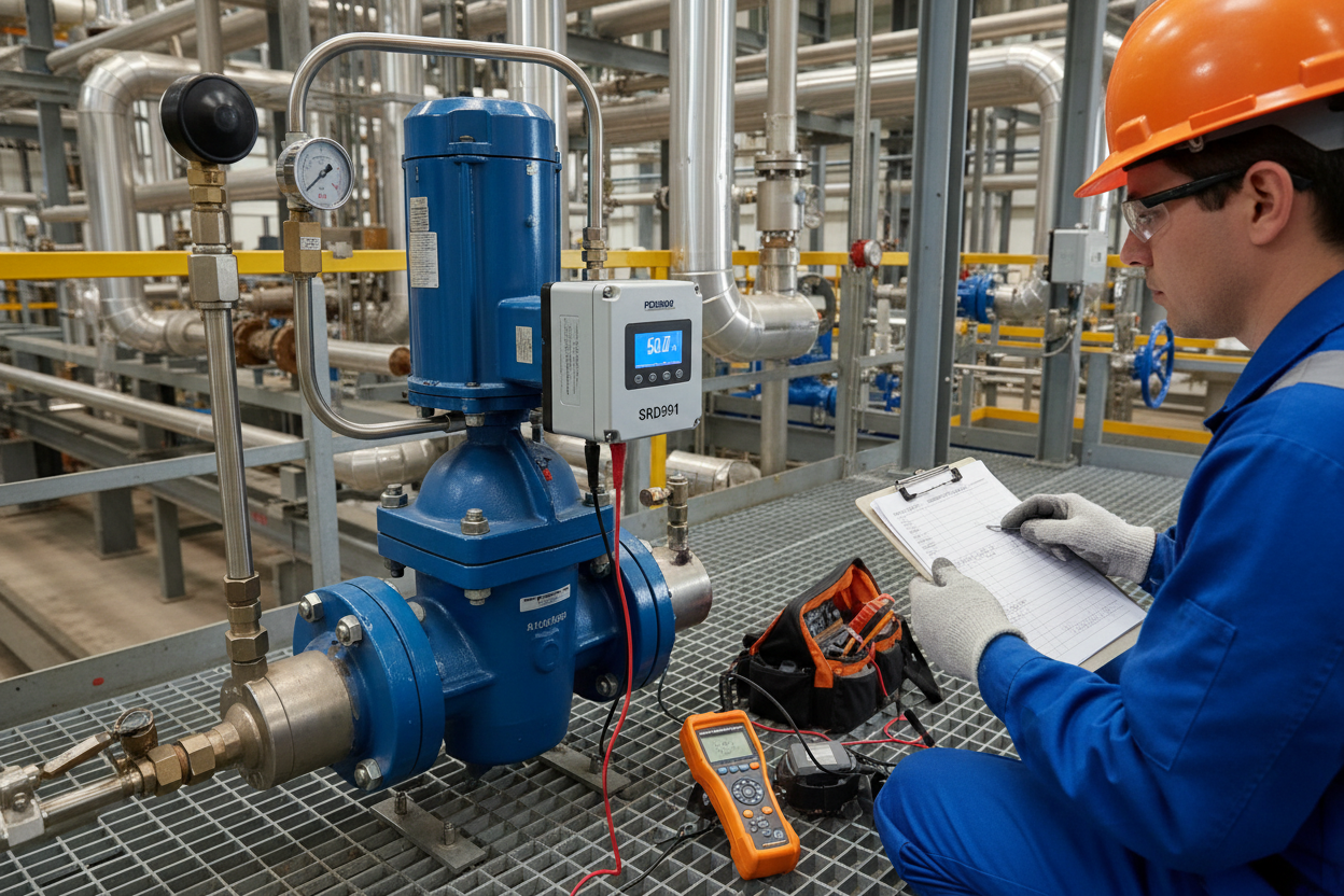
Pneumatic positioners receive a 3 to 15 psi input signal and modulate supply air to position the valve actuator. Smart positioners accept a 4 to 20 mA electronic input, digitize it, and use an internal PID algorithm to drive pneumatic output stages. First, the positioner compares the demanded position with the actual stem or shaft position. Second, it adjusts the output pressure until the error approaches zero. Moreover, smart positioners like the Foxboro SRD991 offer diagnostic data including travel deviation, friction analysis, and cycle counts that support predictive maintenance programs. The Allen-Bradley 1756-OF8H ControlLogix HART Output Module delivers the 4–20 mA control signal to smart positioners and enables HART pass-through diagnostics from the DCS.
Pre-Calibration Safety and Setup
Before calibrating any positioner, place the control loop in manual mode from the Allen-Bradley ControlLogix processor. Isolate or bypass the process if the valve must stroke during calibration. Verify the supply air pressure matches the positioner nameplate rating, typically 20 psi above the maximum output. Furthermore, confirm that the air supply is dry and oil-free, as moisture inside the positioner can cause erratic behavior during calibration. Connect a calibrated current source or loop calibrator to the positioner input terminals. Attach a pressure gauge to the output port to monitor actuator pressure. The Allen-Bradley 1756-OF8IH 8-Point HART Analog Output Module supports isolated channel output for positioner signal delivery in safety-critical valve applications.
Manual Zero-Span Calibration for Pneumatic Positioners
- Step 1: Apply a 3 psi input signal, which corresponds to 0% valve position. The valve should move to its fully closed or fully open position depending on action.
- Step 2: Adjust the zero screw on the positioner until the output pressure just begins to change and the valve reaches the correct mechanical stop.
- Step 3: Apply a 15 psi input signal, corresponding to 100% valve position.
- Step 4: Adjust the span screw until the valve reaches its fully open or fully closed position at the opposite travel extreme.
- Step 5: Return to 3 psi and recheck the zero. Adjustment of the span screw often shifts the zero. Therefore, iterate between zero and span adjustments until both endpoints are correct without further adjustment.
- Step 6: Apply mid-range signal at 9 psi and verify the valve position reads approximately 50% travel.
- Step 7: Record the as-found and as-left values at 0, 25, 50, 75, and 100% travel.
Auto-Tune Calibration for Smart Positioners
Smart positioners simplify calibration through auto-tune functions. On the Foxboro SRD991, enter the calibration menu and initiate the auto-tune sequence. The positioner strokes the valve fully closed and fully open to learn the travel range. It then calculates optimal PID gains for the specific actuator and valve combination. However, auto-tune assumes the mechanical linkage is correctly adjusted. Therefore, verify the feedback lever alignment before initiating auto-tune. A misaligned lever produces incorrect position feedback, causing the auto-tune algorithm to set inappropriate gains. After auto-tune completes, manually verify travel at 0, 50, and 100% using the local indicator. If the position deviates more than 1% at any point, repeat the auto-tune with corrected linkage.
Troubleshooting Common Positioner Problems
Valve hunting, where the stem oscillates around the setpoint, usually indicates excessive gain in the positioner PID algorithm. Reduce the proportional band or gain setting incrementally until oscillation stops. Conversely, sluggish response where the valve creeps slowly to setpoint suggests insufficient gain or a restricted supply air line. Check the air filter regulator for blockages. Moreover, positioner output that saturates at supply pressure despite a mid-range input signal points to a failed feedback linkage or position sensor. On pneumatic positioners, check the relay valve for stuck poppets. On smart positioners, review the diagnostic alarm register before replacing hardware.
Conclusion and Action Advice
Control valve positioner calibration ensures accurate valve positioning and stable loop performance. Use manual zero-span iteration for pneumatic positioners and auto-tune for smart positioners. However, always verify mechanical linkage before calibrating. Finally, record as-found and as-left data at five test points for traceability. Consistent positioner maintenance reduces process variability, extends valve service life, and supports functional safety compliance in SIS-integrated control loops.
Author: Chen Wei is an industrial automation engineer with over 10 years of experience in PLC, DCS, and control systems.


